My Zimaboard 2 is at my leaving room and I want to keep it as quiet as possible. So, I want to use a Noctua fan to cool it. Similar to this topic. However, I didn’t find the fan wiring scheme.
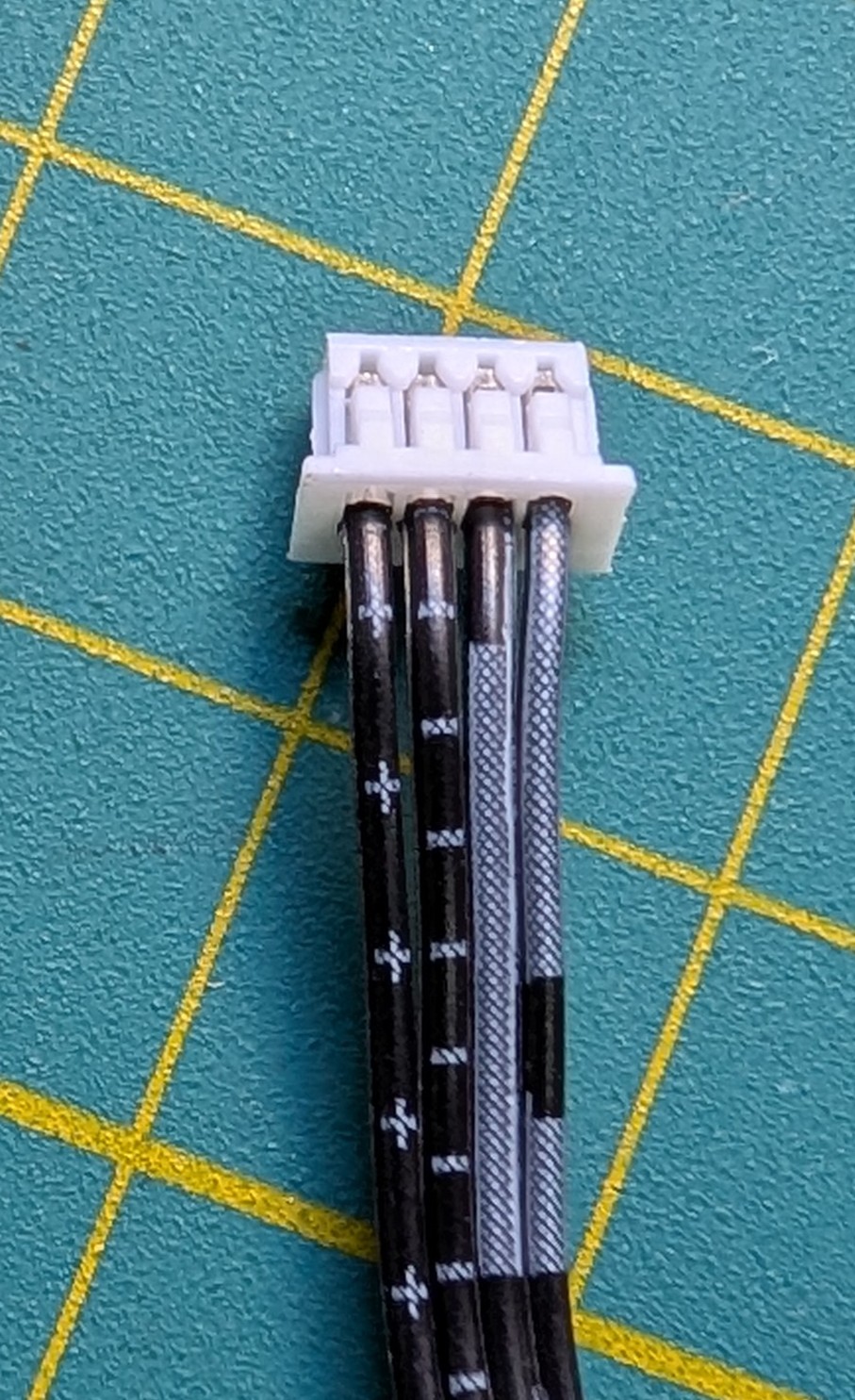
I checked its fan wires but I’m not sure what it means:
The “+” should be 12v and “-” should be GND. I have no idea about the others, which is PWM and which is RPM. Does anyone knows where I can find the wiring scheme?
Thanks for your reply. I checked the wires with a multimeter and it is indeed the standard 4-pin PWM fan header. The symbols in the wires can be ignored.
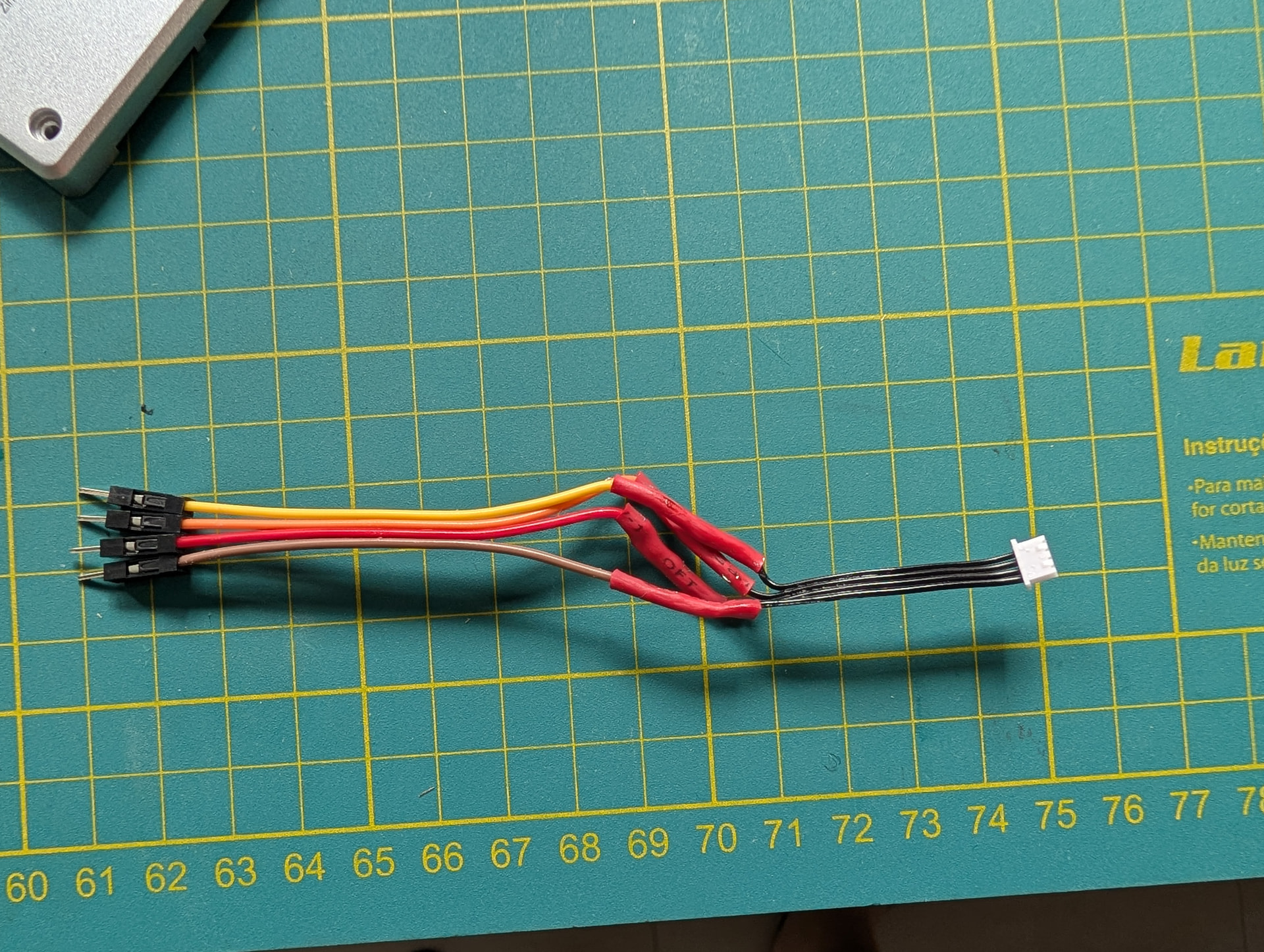
I sacrificed my included fan to use it’s wire, I’m sorry but managed to make it work.
Not the most beautiful soldering job you is going to see today, but it does the job:
I’d like to find a solution quickly. I purchased a Noctua 80mm NF-R8 redux 1800 pwm and a 3d-printed adaptor. I have to rewire the connector since it’s seems it’s nowhere available.
I cannot solder.
Is there a chance to use the Noctua OmniJoin Adaptor Set? Anyone managed to use it?
I hope someone can answer to this topic.
I don’t know the adapter, juts googled it. As I understood you got cut the wire and remove the insulation anyway.
I know it may seems overwhelming but wire soldering like this is pretty simple. My skill is very low, I only do that once each 2 years. I would suggest buy an iron soldering and learn it. Watch a couple videos on YouTube, practice a couple of times in a spare wire and you are good to go. If you fail you can always cut ot more and start again.
If you strictly cannot solder any wire, your best options would be to either (a) use a USB powered fan or (b) to use a splitter cable from the SATA power connector. There will be trade-offs either way and you will have to make a call on that unfortunately.