Fan wiring and resource tutorial for Zimaboard

Hi!

New here! Been a part of the Zimaboard club for a short time but in that short time i’ve learnt alot in relation to Linux, CasaOS and the board itself with the help of all the fellow members on Discord.

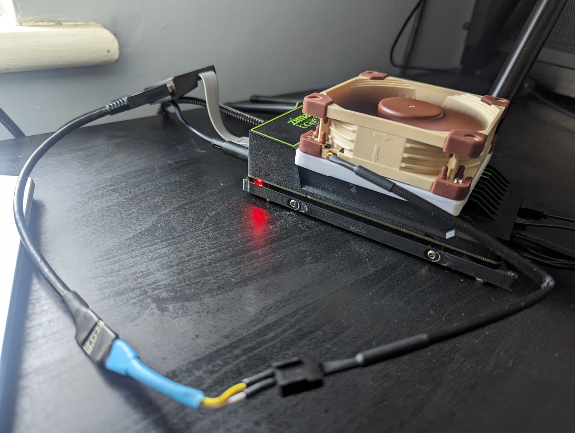
I’m here today to run you through the tutorial on utilising the cpu_fan header on the underside of the board to run a simple fan configuration.

What you need:

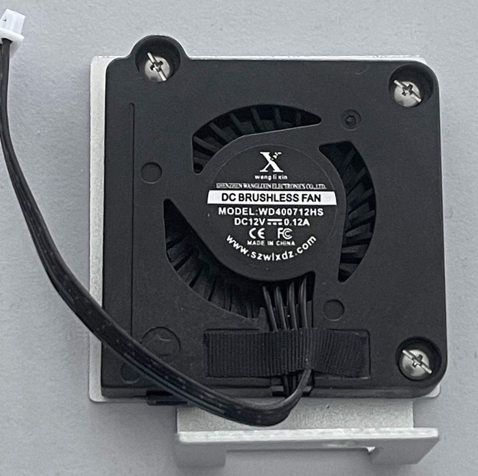
  • 80mm fan or a fan of your size and choosing.
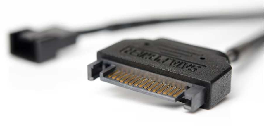
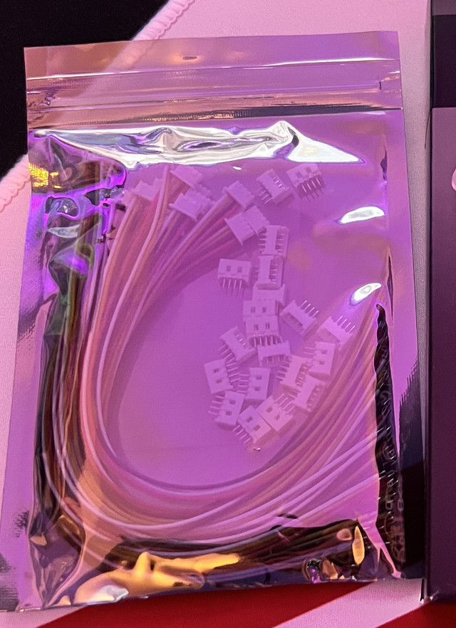
  • Picoblade male connector (pre-wired), the one i bought came under a different name Micro JST MX 1.25mm pitch.
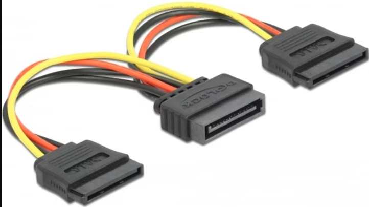
  • Female 3 or 4pin fan connector - I chose to use an old cable i had and snipped off the female end.
  • Soldering iron
  • Solder and flux (optional)
  • Wire stripper
  • Heatshrink
  • Fan resistor (optional to reduce fan speed on 3pin fans)
  • 3D printed fan bracket for Zimaboard - This one was provided to me by Sabitech (Big thanks!)

With those items in mind, though not all are necessary it will definitely make the job a lot easier and will save you alot of time.

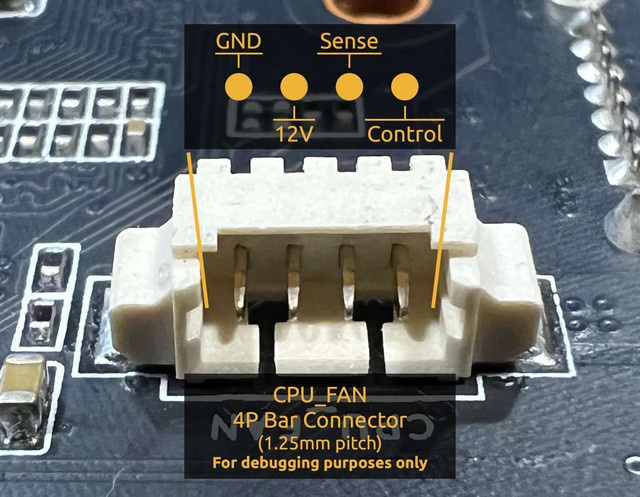
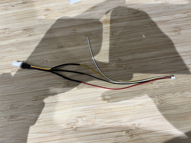
Firstly take a look at the pin out for the connector to determine where each wire should go in relation to the fan pin out.

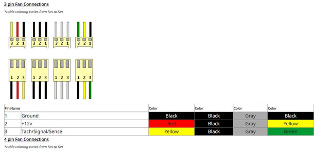
Match each of the pins from the fan cable to the pinout of the connector.

Ground to ground
12v to 12v
Sense to sense
Control to control (in my case this cable isn’t needed due to it being a 3pin fan with no pwm control)

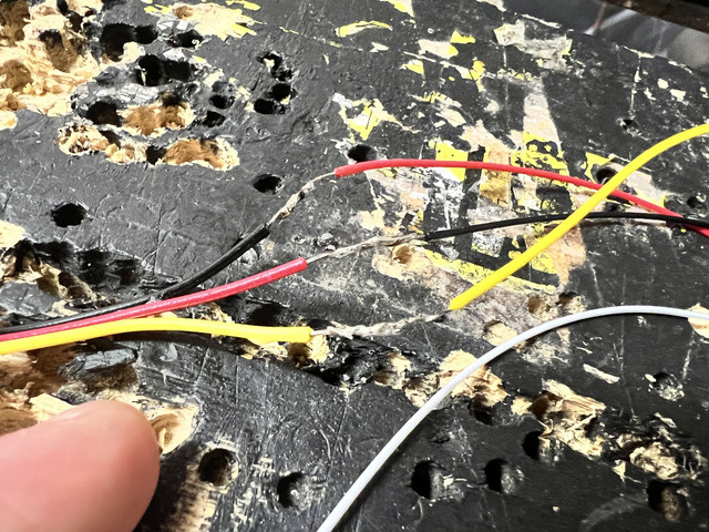
The colour of the wires do not matter, what matters is connecting the correct pin out from the connector on the board to the correct pin on the fan connector. Strip the plastic ends of each wire on both connectors for the Picoblade Male and the Fan connector female. Run the heatshrink onto each wire before twisting the pairs of wires together and apply flux and solder to ensure a secure connection. After this, heat the heatshrink to protect the exposed wiring. In my example i have left the 4th wire, control, incase i need to use it in the future but it can be removed if you are using a 3pin fan.

An alternative to this solution is to cut the fan connector of the fan itself and wire the picoblade connector straight to the exposed ends of the fan. This however permanently modifies the fan where as my method still retains the factory fit of the fan connector and allows you to swap fans if needed.

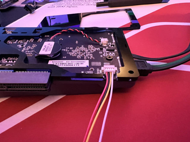
Next job is to modify the existing acrylic bottom piece to allow for the cable to pass through. I made a small cut and removed a small section. You need to be really careful here as the acrylic bends and breaks easily. Take your time and do not rush. Once you have made the appropriate modification it should look something like this:

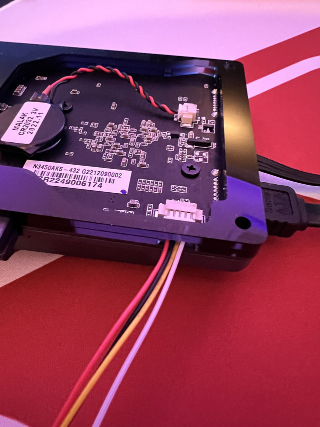
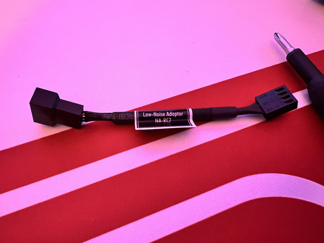
Once this is done, it’s time to test the cable and connect a fan. No configuration in bios is necessary, it should be plug and play and feed 12v power to the fan. If you did everything correctly, the fan should run as soon as you start up your Zimaboard. Use the fan resistor (i had a Noctua one laying around which i repurposed for this) if the fan runs too loud.

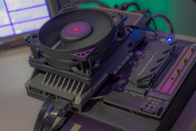
With this mod i dropped my cpu temp down from 35c to 29c and it runs silent.

Any questions, feel free to post here and i will answer them the best i can.

Resource:

You can get the free printable bracket from Sabitech’s Printable page here:
https://www.printables.com/model/608419-zimaboard-80mm-fan-mount

Amazon link to the connectors:
20 Set Micro JST MX 1.25mm 4Pins Connector Plug Socket 1.25mm Pitch Female & Male Connector PCB Socket 150mm Cable: Amazon.co.uk: DIY & Tools

4 Likes

Beautiful! Much better than my original prototype

2 Likes

Couldn’t have done it without your help though, it was you who gave me the original idea! Many thanks for the support case and fan bracket you printed for me :D. Top notch as usual Sabi!

2 Likes

This setup is really really cool!!! Love it! The fusion of black and purple is like magic.

1 Like

it seems a good job but an information: cooler is on all time or switch on when a temperature is reached ?

Any possible updates to work with a Zimaboard 2, perhaps?

Tagging our 3D printing heroes @Sabitech and @LukeOne :slight_smile:

Thank you for sharing your tips! That’s awesome!

Do you (or somebody else) know what the specified maximum current is for the fan header of the ZimaBoard (specifically for ZimaBoard2 actually)?

I was wondering if I could attach a Y-splitter cable in order to then be able to attach 2 fans.

One fan for the usual cooling of the case and the second fan for enhancing the cooling situation of hard drives. Imagine for example the 2 disks are mounted in the official tray from Zima and then attaching a fan vertically in front of it.

For safe operations of operating multiple fans powered by the fan header from the Zimaboard2, it is therefore important to check if the collective current draw is within the specification of the fan header’s maximum current.

Thanks for any information!

I’d consider using a SATA fan splitter, no worries about Zimaboard fan header overdraw.

Do you mean something like that?

First to put a SATA splitter connected to Zima’s SATA Y-cable (since there are still 2x HDD to power, so making out of 2 then 3 SATA connections):

then the 2nd one goes into a SATA-2-4pin-fan adapter (here a product picture of a Noctua adapter for example):

That could power the fan for cooling the HDDs.

If I also want to replace Zima’s small fan for the top side of the case, which comes with ZimaBoard2, let’s say with another fan (like a nice, stronger 80mm one, also 12V powered), do you think it would be still fine to take the power from that onboard SATA (coming via the Y-cable) to drive 2x 12V fans without any issues for anything in this built?

So each of the Y-cable SATA connectors gets their own SATA 1-to-2 splitter (first photo above) attached, so ultimately 2x HDDs and 2x 12V fans are powered?

Hmmm I thought for sure one could find a short sata cable extension with fan headers on it, would make this a piece of cake to get done. Alas I searched quite a bit and cannot.

So yes you could use the solution you found but it would get messy imo. There’s a reason I always wind up building small x86 ITX systems for small NAS builds, instead of the much cooler looking ones :thinking: .

Rethinking it, and looking at the Zima SATA cable, it would be super easy to tap into into the SATA +12V/GND lines and attach a couple of fan header sockets.

Rethinking it, and looking at the Zima SATA cable, it would be super easy to tap into

I tried to look for various cable/adapter products, but also couldn’t find anything yet. As for tapping into it, unless that’s possible just by adapters, I’d at the moment not want to try it in order not to create any follow-up issues, so I want to let original Zima pieces as they are.

Rethinking as well, I realized (again) that their Y-cable features 22pin SATA, and maybe there might be possibilities with separate 15 + 7 adapters, but it would end up in a very messy chain of adapters, partially likely not using the existing data ones from Zima’s cable, but instead would have to add another set of data-only SATA cables into the mix as well and so on. It doesn’t feel right.

Also, but I’m not sure, can it be the PWM signal would be only available from the actual fan header? When I want to benefit from PWM-controlled fans, then I guess there is only one option: to go from the fan header. Or?

Now, I also was searching the net for ready-made products for that particular Molex Picoblade aka JST 1.25mm type of port, but it seems really not well spread, at least not ready made. Hence I guess this whole thread started with this: it needs tbd in a custom built. So I think the cleanest seems still to build a custom cable, which features a regular 4-pin PWM fan header on the one end and on the other the JST 1.25mm. Then attaching a regular PWM-splitter in order to finally attach 2 PWM fans.

But before I can start with this, I need to know the specified maximum current on that small fan header on the ZimaBoard2. I could imagine it should work for 2 fans, but then I also don’t want to just try it out and in worst case end up with a fried ZimaBoard2.

Can an official Zima support staff please help and find out this information?

The standard fan coming with ZimaBoard2 is specified 12V/0.12A (which I think is for that fan quite high, when compared to other fan products on the market). I could imagine the fan header is specified for max 1A? But I need to have this confirmed 100% before I try attaching 2x fans running on that tiny fan header.

Thanks!

Short question regarding the bracket, where you mounted the fan on:

you just have placed then whole unit onto the ZimaBoard just like that? It is not further fixed somehow?

Thanks

  1. An extra Zima SATA cable is only $4 USD so you can keep your original intact, and resistors are cheap. Mod at your hearts content and done.

  2. If PWM is needed: https://shop.alphacool.com/en/shop/fans/controller/lz-alphacool-core-10x-4-pin-pwm-splitter-with-sata-power-connector?currency=3

  3. My typical case fans are marked 1-2W. The Zima fan is right in there.

re #2: Admitting I’m new to the PWM topic, but my understanding is the PWM signal needs to be fed in this product also via a separate input, which is done by connecting the splitter - next to SATA for power - to the mainboard. Else there won’t be a PWM signal reaching the splitter and could not control the fans. Fans would run on 100% always then. The PWM control signal needs to come still - imho - from the fan header of the ZimaBoard2.

re #3: Ok, it might be generally for a fan still being in the usual specs. What I meant was in relation to its size and comparing to products from Noctua for example, I find it too high, when a much larger and seemingly more sturdy construction from Noctua (80mm fan) uses 0.75W for example.

0,75W? What is holding you back just go motherboard connector and done.

I want to drive 2 fans from the fan header.

Yes you did specify that. IMO this is getting way to complicated, best of luck.